Tool: Behavior Editor
The Behavior Editor controls advanced settings for models and animations. The editor window houses two closely related editors, the Behavior Editor, which controls advanced game features like ragdolls and turrets, and the Track Set Editor, which allows masking animation to only certain parts of a model. The Behavior Editor stores its data in the scene on a node of type SC2BehaviorHolder. It is important not to delete or hide this node.
Common Controls
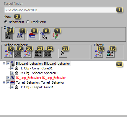
Target Node identifies the SC2BehaviorHolder node in the current Scene that the editor is currently editing. It is uncommon to have more than one of these in a scene. If no node is found, one will be automatically created when a Behavior or TrackSet is added.
Show switches the editor between Behavior and Track Set mode. The List Box will be updated to display the appropriate type of data, and the applicable buttons will be enabled or disabled.
Add Track Set will, when in Track Set Mode, add a new TrackSet onto the Target Node. This will appear and be editable in the List Box below.
Add IK Leg Behavior will, when in Behavior Mode, add a new IK Leg Behavior onto the Target Node. This will appear and be editable in the List Box below.
Add Turret Behavior will, when in Behavior Mode, add a new Turret Behavior onto the Target Node. This will appear and be editable in the List Box below.
Add Billboard Behavior will, when in Behavior Mode, add a new Billboard Behavior onto the Target Node. This will appear and be editable in the List Box below.
Add Physics Joint Behavior will, when in Behavior Mode, add a new Physics Joint Behavior onto the Target Node. This will appear and be editable in the List Box below.
Add Bones From Viewport Selection will use the currently selected nodes in the main 3ds Max Scene in the Behavior or Track Set currently selected in the List Box. This can add multiple nodes at one time, and is the primary mechanism for adding bones to Turrets, Billboards, and TrackSets.
Pick Bones From Viewport adds one bone at a time to a Behavior when there are specific validations that must be done. This is the primary mechanism for adding nodes to IK Leg Behaviors and Physics Joints Behaviors.
Select All Bones in Viewport will use the current selection in the List Box to select nodes in the main scene.
Add Material or Texmap from Active Material Editor Slot adds a material or texture via material browser. It is important to note that only properties of a single level would be available for enabling. For instance, in order to add the uvOffset of a texture map to a track set, the texture map itself needs to be added, not the material that’s using it.
Put Material or Texmap in Active Material Editor Slot will replace the current item selected in 3ds Max's material editor with the material currently selected in the List Box.
Delete Selected Node will remove the item currently selected in the List Box. This will remove behaviors, track sets, or members of either as appropriate.
Filter By Selected Bones shows only Behaviors and Track Sets that contain models that are selected in 3ds Max. While all other Behaviors and Track Sets will remain active, they will not show up in the List Box. This filter is active if the button appears depressed.
Filter By Selected Material shows only Track Sets that contain the SC2 Material or SC2 Bitmap currently selected in the Material Editor. While all other Track Sets will remain active, they will not show up in the List Box. This filter is active if the button appears depressed.
List Box is the primary overview panel in the Behavior Editor. Depending on the mode, it will list either Track Sets or Behaviors. Data is presented in a tree structure, with each type of Behavior controlling the nature of the items within it. Details of these structures are provided in the modal breakdowns below. Red items denote a Behavior with an error; tracks assigned may be deleted or no longer valid. TrackSets can become red if they are not used in any animations. Clicking items in this box will select them in the Viewport. Shift or Ctrl Click can be used to add to the selection.
Track Sets
When in Track Set Mode, the Behavior Editor List Box will be updated to contain all TrackSets defined for the given SC2BehaviorHolder. Items that are checked in this mode will export their animation when assigned to a given Animation in the Anim Prop Floater. Unchecked items will be skipped.
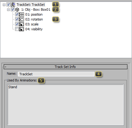
Track Set lists all TrackSets in the scene that satisfy Filter By Selected Bones and Filter By Selected Material if either are active. Names of Track Sets are listed as the second part of the line, and may be edited with the Name (Track Set) text box.
Track Set Member lists all items that belong to a given track set. TrackSets can contain both Materials and Scene nodes. A single node may be in multiple Track Sets; the union of their checked channels will be used at export.
Track Set Item lists specific channels to use within a node. Track Sets do not have to control an entire node or material. It is often beneficial for a given animation to only control a subset of parameters, and this allows this control. For performance reasons, many parameters are necessarily covariant, and the StarCraft II Art Tools will only let you turn on and off the group. For example, X Y and Z rotation will always be considered together.
Name (Track Set Info) allows for renaming track sets. Changes here will automatically update any animations referenced in Used By Animations
Used By Animation lists all the animations that the currently selected Track Set is referenced by. This is the corollary to Add (Track Set) in the Anim Prop Floater.
Inverse Kinematic Behaviors
This behavior attempts to make feet snap to terrain instead of floating above or below ground. It will use Bone 2 (IK_Leg_Behavior) and the tolerances defined by Max Search Up and Max Search Down to attempt to locate a suitable position for the foot, and then relax all bones between Bone 1 (IK_Leg Behavior) and Bone 2 (IK_Leg_Behavior) so that the joint chain looks natural. The joint chain must include at least 3 joints, including Bone 1 (IK_Leg_Behavior) and Bone 2 (IK_Leg_Behavior).
Inverse kinematic (IK) behaviors are specifically coded to support cliff-walking for the Colossus in StarCraft II: Wings of Liberty. It is not advisable to use this feature in Custom Mods at this point in time.
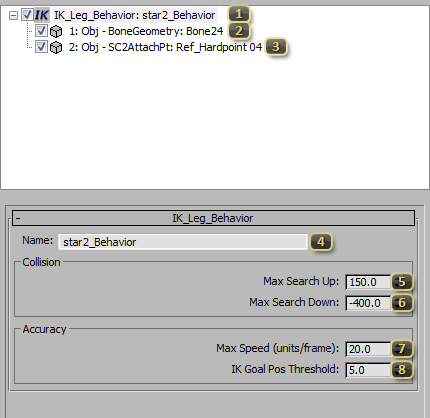
IK_Leg_Behavior lists all the Inverse Kinematic behaviors in the scene that satisfy Filter By Selected Bones. Names of these behaviors are listed on the second part of the line, and may be edited with the Name (IK_Leg_Behavior) text box.
Bone 1 (IK_Leg_Behavior) sets the first bone in the IK joint chain. This bone, and all children leading to Bone 2 (IK_Leg_Behavior) will partake in the IK behavior.
Bone 2 (IK_Leg_Behavior) sets the last bone in the IK joint chain. The location of this bone is the point that will be used to test for, and resolve, collision with the ground.
Name (IK_Leg_Behavior) allows for renaming the leg behavior. This name is for organizational purposes only.
Max Search Up denotes how far above the location of Bone 2 (IK_Leg_Behavior) the IK solver should look for something to stand on.
Max Search Down denotes how far below the location of Bone 2 (IK_Leg_Behavior) the IK solver should look for something to stand on.
Max Speed (units/frame) defines the furthest distance Bone 2 (IK_Leg_Behavior) can move in a single frame to try to get to the IK Solver's preferred location, provided one was found.
IK Goal Pos Threshold specified how close the solver must get the leg before it is considered close enough to be at the position. Higher values here prevent jittering, while lower values make for more accurate final contact points.
Turret Behaviors
Turret Behaviors allow a subset of bones in a character to point in a direction procedurally. For example, head and neck bones may be placed in a Turret Behavior so that a character can be told to look at objects dynamically in the Cutscene Editor. Turret Behaviors have a manipulator per-node to control their alignment. The Forward Vector of the manipulator will point towards the target location. The node's orientation will remain relative to the manipulator.
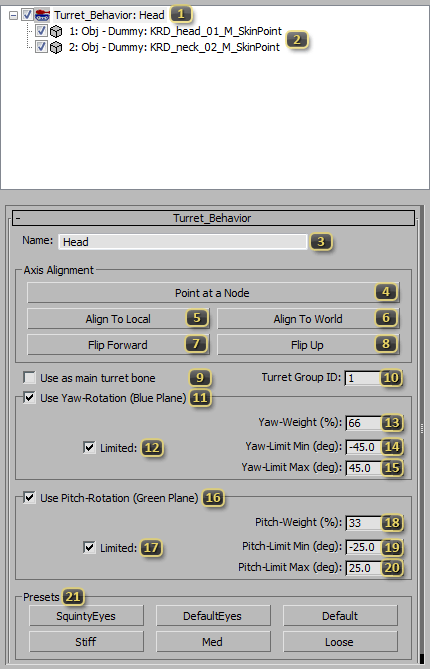
Turret_Behavior is a group of bones that can be enlisted in a Look At Type in the Game UI Data The name, which is editable by Name (Turret_Behavior), must match an ID in the Data: Look At Types.
Turret Bone Array shows all bones that are in a given Turret_Behavior.
Name (Turret_Behavior) defines the ID by which the given Turret Behavior can be accessed. It must match one of the types defined in a loaded Mods Game UI Data to be considered. The default list includes:
- EyeLeft
- EyeRight
- EyeHead
- Chest
- Turret_Left
- Turret_Right
Point at a Node enters a picking mode, where selecting a scene object will orient the currently selected turret manipulator towards the chosen target.
Align To Local snaps the manipulator to match the local transform of the node. The Forward Vector will match the Negative Y Axis.
Align To World snaps the manipulator to match the scene's world axes at the location of the node. The Forward Vector will match the Negative Y Axis.
Flip Forward reverses the direction of the manipulator's Forward Vector.
Flip Up reverses the direction of the manipulator's Up Vector.
Use as main turret bone will use the relationship of this turret bone and its target as the basis for all other turret bones with the same Turret Group ID. By default, every turret bone will align its forward vector directly at the look at target. If a turret bone has this option set, relative offsets will be used instead. That is to say, if the Head is the main turret bone, and the chest was also a turret, the chest would point towards a point below wherever the head was looking. There can only be one main turret bone per turret group.
Turret Group ID is a number which defines a group for which there can be a Main Turret Bone.
Use Yaw-Rotation (Blue Plane) allows the turret to move freely around its Up Axis. This range of motion is displayed by the Blue Plane on the manipulator.
Limited (Yaw) locks the range of Yaw movement. If disabled, the turret can move 360 degrees around the axis.
Yaw-Weight (%) regulates how completely the controlled node should face the target. Using smaller values is often useful for reducing the influence down a joint chain, such as in a human neck.
Yaw-Limit Min (deg) corresponds to the furthest negative rotation around the turret's Up Axis that is allowed.
Yaw-Limit Max (deg) corresponds to the furthest positive rotation around the turret's Up Axis that is allowed.
Use Pitch-Rotation (Green Plane) allows the turret to move freely around its Left Axis. This range of motion is displayed by the Green Plane on the manipulator.
Limited (Pitch) locks the range of Pitch movement. If disabled, the turret can move 360 degrees around the axis.
Pitch-Weight (%) regulates how completely the controlled node should face the target. Using smaller values is often useful for reducing the influence down a joint chain, such as in a human neck.
Pitch-Limit Min (deg) corresponds to the furthest negative rotation around the turret's Left Axis that is allowed.
Pitch-Limit Max (deg) corresponds to the furthest positive rotation around the turret's Left Axis that is allowed.
Presets are common configurations for the above properties. They will overwrite the values already defined for Yaw and Pitch properties.
- SquintyEyes have more lateral movement than vertical.
- DefaultEyes are a decent place to start for most human eyes.
- Default is the tool standard, providing hemispherical movement.
- Stiff provides minimal freedom, often a good starting point for the base of the spine.
- Med provides moderate freedom, useful for leading into bones with more freedom.
- Med provides a large amount of freedom, useful for the chest and other high-movement areas.
Billboard Behaviors
Billboard Behaviors align a bone in the scene to the camera. The bone can be set to pivot around the node's local-space axes, the game world-space axes, or freely move to match the camera. In most configurations, the node's local Z Axis will try to align with the Camera's Up Vector, and the node's local Y Axis will align with the Camera's Forward Vector. The side facing the Negative Y Axis will face the camera.
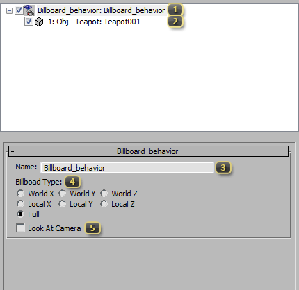
Billboard_behavior lists all Billboard Behaviors that satisfy Filter By Selected Bone. Names of these behaviors are listed on the second part of the line, and may be edited with the Name (Billboard_behavior) text box.
Billboard Bone Array is the list of all bones that share this set of billboard settings. Each bone pivots on its own position. If many bones are to pivot together, only their parent should be added.
Name (Billboard_behavior) allows for renaming the Billboard Behavior.
Billboard Type defines the rotational axis of freedom for the Billboard to pivot around. If Full is selected, the Yaw, Pitch, and Roll of the node will be freely aligned to the camera.
- World [X/Y/Z] pivots only on the specified world aligned axis.
- Local [X/Y/Z] pivots only on the specified node local axis.
- Full always points directly at the camera.
Look At Camera causes the Billboard to turn in towards the center of the camera when off to the sides. Otherwise the Billboard will align with the orthographic Camera Forward Vector.
Physics Joint Behaviors
Physics Joints connect two SC2Physics nodes to each other. The Domino Physics System used by StarCraft II is most stable when physics bodies are connected from most massive to least massive. This Behavior is used to create the "Ragdoll" Death models in StarCraft II: Heart of the Swarm. Joint Behaviors have a reference frame for each connected body. The reference frames will align as soon as the joint is enabled in the Physics System. Frames are aligned from the root of any joint hierarchy. Order of evaluation of siblings is undefined. It is recommended that reference frames are located within the bounds of their SC2Physics node, for increased stability.
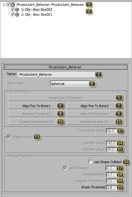
PhysicsJoint_Behavior lists all Physics Joint Behaviors that satisfy Filter By Selected Bone. Names of these behaviors are listed on the second part of the line, and may be edited with the Name (PhysicsJoint_Behavior) text box.
Bone Pair (PhysicsJoint_Behavior) lists the two bones engaged in a Physics Joint. They must have SC2Physics nodes as children. When the behavior is selected, reference frames for the joint will be visible in the Viewport. When resolving the joint, these two bones are moved so that the reference frames are aligned. Bones are added in the order they are selected in Pick Bones From Viewport.
Name (PhysicsJoint_Behavior) allows for renaming the Physics Joint Behavior
Joint Type specifies the way a joint should move. There are several styles to choose from:
- Spherical allows the joint to move freely about any axis.
- Revolute allows freedom along only a single axis, like a door hinge.
- Cone lets the joint move freely like a Spherical joint, but constrains the movement to only Cone Angle (deg) away from the default position.
- Weld restricts all rotational freedom, locking two physics bodies to each other. Weld joints resist movement in all directions, but are not perfectly rigid.
Reset Axis To Default returns the reference frames to their default location, the pivot of the second bone in Bone Pair (PhysicsJoint_Behavior).
Align Pos To Bone1 moves the reference frame of the currently selected bone(s) to position of the pivot for the first bone in Bone Pair (PhysicsJoint_Behavior). The rotation is unchanged.
Align Pos To Bone2 moves the reference frame of the currently selected bone(s) to position of the pivot for the second bone in Bone Pair (PhysicsJoint_Behavior). The rotation is unchanged.
Align Rot To Bone1 orients the reference frame of the currently selected bone(s) to the rotation of the pivot for the first bone in Bone Pair (PhysicsJoint_Behavior). The position is unchanged.
Align Rot To Bone2 orients the reference frame of the currently selected bone(s) to the rotation of the pivot for the second bone in Bone Pair (PhysicsJoint_Behavior). The position is unchanged.
Rotate Forward Axis 90 adjusts the rotation of the reference frame along the local Z Axis. This is most useful for Cone and Revolute Joint Types where it can be used to control the center of the Limit Min and Limit Max.
Rotate Up Axis 90 adjusts the rotation of the reference frame along the local Y Axis. This is most useful for Revolute Joint Types where it can be used to quickly reorient the freely moving axis.
Cone Angle (deg) defines how far a Cone Joint Type can move from its default position.
Enable Limits enforces constraints on Revolute and Cone Joint Types for movement around the local Z Axis.
Limit Min (deg) represents the furthest possible negative rotation from the default joint orientation.
Limit Max (deg) represents the furthest possible positive rotation from the default joint orientation.
Use Shape Collision allows the two connected bodies to collide with each other. Normally this is undesirable, because the two SC2Physics nodes will always be in contact, and colliding them can produce unexpected results, such as jittering. Even with this option off, physics bodies that are not directly connected by a Physics Joint Behavior will still collide.
Joint Friction causes bodies to lose energy as they rotate along a joint. This causes their movement to slow. Disabling this property, or using a low value represents a slippery joint. Higher values resist movement.
Damping Ratio controls the springiness of a Weld Joint Type. A value of 1 will attempt to reach the proper direction in the shortest time possible. Lower values may overshoot and wiggle. Higher values will swing into place slower.
Angular Frequency controls the strength of a Weld Joint Type. Higher values will appear to lock into place quicker and more completely. Lower values may never reach their target, and may appear limp.
Break Threshold *exported but unused* Intended to be between 0-1 to determine joint strength. 0 denotes a fragile joint; a value of 1 is unbreakable.